High rejection rates from metal cutting are expensive — not just for material and labor, but for reputation, lead times, and customer trust. The good news: most rejection causes are predictable and fixable. In this long-form guide you’ll find a practical roadmap combining process controls, operator practices, inspection strategies, and machine-selection advice so you can drive rejection rates down and productivity up.
Executive summary (what you’ll learn)
-
The most common causes of cutting rejections (material, machine, program, consumables, environment).
-
Practical fixes: machine settings, maintenance, fixturing, part nesting, and post-processing.
-
Inspection & measurement strategies that catch defects early.
-
Data-driven approaches: SPC, root-cause analysis, and continuous improvement.
-
How the right machine choices (laser type, power, automation) reduce rejections long term.
-
A checklist you can implement today.
Why rejection rates matter
Rejection = wasted material + wasted machine time + rework + delayed shipments. Even a small percentage point drop in rejection rate often pays back quickly. Aim for continuous improvement: set realistic targets (e.g., reduce rejection by 30% in 90 days) and track progress.
Top causes of metal cutting rejections (and how to spot them)
1. Material variability and defects
Symptoms: inconsistent edge quality across batches, unexpected warpage, slag or oxide on cut faces.
Root causes: wrong alloy, inconsistent thickness, residual stresses, rust, coatings, mill scale, or hidden hardness variations.
Fixes:
-
Inspect incoming materials: measure thickness, check certificates, and sample-cut test pieces.
-
Establish accepted suppliers and quarantine new batches until signed off.
-
Use pre-cut cleaning (degreasing, de-rusting) for contaminated stock.
-
For coated materials, test cut parameters — coatings change absorption and may require different gas or power.
2. Poor machine setup or maintained optics
Symptoms: uneven kerf, excessive dross, inconsistent piercing, smoke or soot accumulation.
Root causes: misaligned optics, dirty lenses/mirrors, worn nozzles, bad focus, unstable power supply.
Fixes:
-
Schedule daily/weekly optical inspections and cleaning. Follow manufacturer SOP for lens handling.
-
Replace consumables (nozzles, shields) on the manufacturer’s recommended interval or when quality degrades.
-
Use machine-level power conditioning and monitor voltage stability.
-
Verify focal position with test cuts — focus drift causes poor edge finish and increased thermal distortion.
3. Wrong cutting parameters (power, speed, gas)
Symptoms: burning, heavy dross, slow penetration, taper, excessive melt-back.
Root causes: parameter mismatch for material/thickness, wrong assist gas or pressure, incorrect nozzle-to-work distance.
Fixes:
-
Maintain and continually refine a parameter library: material × thickness → power, speed, frequency, gas pressure, nozzle size, focal offset.
-
When using lasers, use recommended pulse/continuous modes per material.
-
For oxyfuel/laser/gas processes, test incremental changes and capture results (photos + measurements).
4. Bad nesting, clamping, or fixture design
Symptoms: parts bent during cutting, shifted holes, inaccurate tolerances after release.
Root causes: poor fixturing, inadequate support causing vibration/warpage, thermal expansion not accounted for.
Fixes:
-
Design fixturing that anchors and supports key datum features. Use slotted or floating clamps for thermal growth.
-
Sequence cuts to minimize free-standing thin sections early in the job.
-
Add bridges/tab features where parts might move, and automate tab-break processes if possible.
5. Programming/CAD/CAM issues
Symptoms: mis-positioned holes, wrong part orientation, unnecessary lead-ins or microjoints left.
Root causes: wrong origin, incorrect kerf compensation, unoptimized cutting order.
Fixes:
-
Standardize CAD/CAM templates: consistent origin points, kerf offsets, and lead-in/lead-out rules.
-
Simulate cutting paths and do a dry run (no cut) to verify tool paths.
-
Use nesting software that supports collision checks and optimized cut sequencing for heat and material stress.
6. Operator skill gaps and inconsistent practices
Symptoms: variable results shift-to-shift, inconsistent application of setup routines.
Root causes: lack of training, shortcuts, no standardized checklists.
Fixes:
-
Implement structured operator training and certification.
-
Use checklists for setup, daily maintenance, and shift handover.
-
Empower operators to stop jobs when they detect abnormal signs and to log issues into a problem tracking system.
Practical, hands-on techniques to lower rejection rates
Start with the basics — inspection of incoming material
-
Verify material certs, thickness variance, and flatness.
-
Keep a sample-cut log per batch: cut 2–3 representative test parts from each coil/plate and record edge finish, dimensional accuracy, and micrograph if necessary.
Standardize and document settings
-
Create an accessible parameter library (paper/online) containing: material, thickness, machine ID, power, speed, assist gas & pressure, nozzle type, focus offset, and expected cut quality photos.
-
Use machine-side parameter locking to prevent accidental changes by operators.
Optimize nesting & sequence for thermal control
-
Use nesting strategies that reduce heat buildup: spread high-heat cuts, avoid clustering small high-heat parts together, and sequence to allow cooling.
-
For thin sheets, cut internal contours before the exterior to reduce distortion.
Control gas quality & pressure
-
Use clean, dry, and oil-free gases for cutting. Contaminated gas increases dross and causes inconsistent cuts.
-
Install online gas pressure monitors and alarms; record gas usage and correlate with quality.
Improve cutting edge life-cycle management
-
Track nozzle and lens life by hours/cuts and condition. Replace proactively rather than reactively.
-
Keep spare sets of consumables to avoid rushed rebuilds that compromise quality.
Build in-process inspection
-
Implement quick inspection steps mid-run: measure critical features on the first and nth part (n depends on run length—e.g., every 50–100 parts).
-
Use simple jigs/gauges for pass/fail checks; for critical parts use CMM or optical measurement periodically.
Introduce process control charts (SPC)
-
Track key metrics like kerf width, burr height, hole diameter, and straightness. Use control charts to detect process drift before large batches are affected.
-
Set warning and action thresholds: e.g., if burr height increases by X% or hole diameters drift beyond tolerance, stop and investigate.
Root cause analysis for each rejection type
-
Use 5 Whys and Fishbone diagrams to isolate causes. Keep a log of RCA results and corrective actions so problems aren’t repeated.
-
Make corrective actions visible on the shop floor (e.g., Kanban, bulletin boards).
Continuous improvement and Kaizen
-
Hold short improvement huddles weekly to review defects and preventive actions.
-
Reward teams that reduce rejection rates or implement effective improvements.
Machine selection: choose smart to reduce rejections
Picking the right machine is a long-term investment in quality. The wrong machine choice increases rework, downtime, and scrap.
1. Laser vs. oxyfuel vs. plasma: consider part requirements
-
Fiber laser: best for thin-to-medium ferrous and non-ferrous metals with fine edges, narrow kerf, minimal dross. Ideal for precision parts and high automation.
-
Plasma: cost-effective for thicker, less precise cuts; faster on certain steels but generally more dross and wider kerf.
-
Oxyfuel: good for thick mild steel when edge finish is less critical; slower and more heat-affected zone.
Choose based on required tolerances, edge finish, material mix, and throughput.
2. Power rating and beam quality
-
Match laser power to the thickness and material mix you cut most. Avoid chronically underpowered machines that force slow speeds and poor quality.
-
Beam quality (M²) affects kerf profile and cut edge. Better beam quality = cleaner, straighter cuts.
3. Automation and material handling
-
Automated loading/unloading, skeleton removal, and part sorting reduce manual handling errors and speed up operations.
-
Integrated gas control, nozzle auto-change, and self-calibration features help maintain consistent cut quality.
4. Closed-loop control and diagnostics
-
Machines with built-in sensors (monitoring gas pressure, focal position, optic contamination) allow predictive maintenance and fewer surprises.
-
Look for machines that log process data so you can correlate conditions to quality issues.
5. Support and parts availability
-
Choose manufacturers with local support, quick spare parts delivery, and training programs. Downtime waiting for parts is a major cause of rushed repairs and poor-quality cuts.
Inspection and metrology: catch defects early
Visual & manual checks
-
First-piece inspection for every new batch.
-
Use light-table or backlighting to spot burn marks, slag, or incomplete cuts.
Dimensional checks
-
Use gauge blocks, plug gauges, or Vernier calipers for quick dimensional checks.
-
For high precision, use CMM or optical scanners on sample parts.
Edge quality metrics
-
Define acceptance criteria for burr height, dross percentage, and edge roughness (Ra). Measure and log them.
-
Photograph representative parts and keep a visual library of acceptable vs. reject conditions.
Non-destructive tests (NDT) if needed
-
For safety-critical parts, consider dye-penetrant or ultrasonic checks to find micro-cracks produced by heat or mechanical stress.
People & training: the human factor
-
Standardize training: operators must know how to read the parameter library, perform daily maintenance, inspect optics, and interpret control charts.
-
Pair new operators with experienced ones for a handover period. Use written SOPs and video tutorials.
-
Encourage reporting culture: near-miss logs help prevent defects before they escalate.
Process documentation & traceability
-
Keep a digital log for each production batch: machine used, operator, material batch number, parameters, and inspection results. Traceability reduces time spent on RCAs and speeds up corrective actions.
Quick wins you can implement in 30 days
-
Daily optics and nozzle checklists — stop 20% of immediate quality loss.
-
First-part sign-off — require inspection and sign-off on the first part of every job.
-
Parameter library cleanup — remove outdated entries and validate.
-
Operator refresh training — one-day focused workshop on common rejection causes.
-
Incoming material sampling — cut & log test coupons from each new batch.
KPIs to track
-
Rejection rate (parts rejected / parts produced) — daily, weekly, monthly.
-
Downtime minutes lost due to quality-related stops.
-
Consumable replacement interval (hours/cuts per nozzle).
-
First-pass yield (FPY).
-
Time to detect & time to repair (TTD, TTR) for defects.
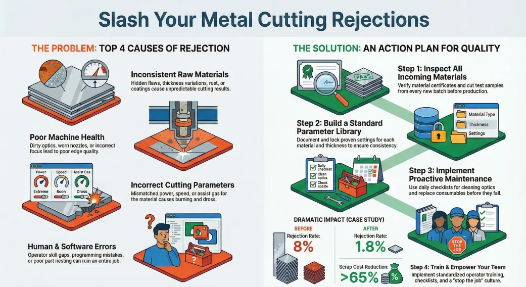
Example case study (high level)
A medium-sized fabrication shop was seeing 8% rejection on a thin-stainless product due to burrs and inconsistent hole diameters. Actions taken:
-
Implemented incoming material coupons (discovered thickness variance).
-
Standardized laser parameters and locked them for the job.
-
Replaced worn nozzles and trained operators on focus checking.
-
Added first-piece CMM verification.
Result: rejection dropped from 8% to 1.8% in 60 days; scrap cost reduced by >65%.
When to call in specialists
-
If you have mysterious intermittent defects (sometimes perfect, sometimes bad), ask for a process audit.
-
If thermal distortion persists despite best practices, consult with a metallurgist or the machine OEM.
-
For multi-material operations, ask for a materials science review to create cross-material parameter sets.
Final checklist (action plan)
- Implement first-piece inspection for every new job.
- Create and maintain a materials incoming inspection log.
- Build a validated parameter library and lock parameters during production.
- Schedule daily optics/consumable checks and replace proactively.
- Optimize nesting and cut sequencing to control heat.
- Train operators and create SOPs + checklists.
- Start SPC for critical dimensions and track in control charts.
- Keep traceability data for each batch (material batch, operator, machine, parameters, inspections).
Closing — long-term approach and solution partner
Reducing metal cutting rejection rates is a mix of discipline, the right machine choices, empowered people, and continuous data-driven improvement. Small, consistent changes—like cleaning optics daily, standardizing parameter libraries, and instituting first-piece inspections—compound into big savings.
If you’d like a partner to accelerate improvements: specialized providers of laser cutting machines and process audits can help implement the fixes above faster. They can run on-site audits, supply matched machines (fiber lasers for fine work, higher-power lasers for thicker metals), provide training, and support automation to remove human variability.
SLTL Laser Cutting Solutions (example partner) specializes in high-precision fiber lasers, automation modules, and process consultancy that directly reduce rejection rates and improve first-pass yields. They combine machine choice, tooling, and operator training to help shops “fix them fast” and sustainably. (If you want, I can draft an audit checklist or a tailored improvement plan for your shop — tell me your most common rejection types and I’ll make a prioritized action roadmap.)
Author Bio

Mayank Patel
R&D HeadMayank Patel is the Head of Research & Development at SLTL Group, bringing over 20+ years of hands-on experience in the field of laser technology. A forward-thinking innovator, he has played a pivotal role in developing advanced laser cutting, welding, and marking solutions tailored for diverse industries. Under his leadership, SLTL’s R&D division continues to push the boundaries of what laser systems can achieve in modern manufacturing.